


Optical Flow Sensor
Optic Flow Module:
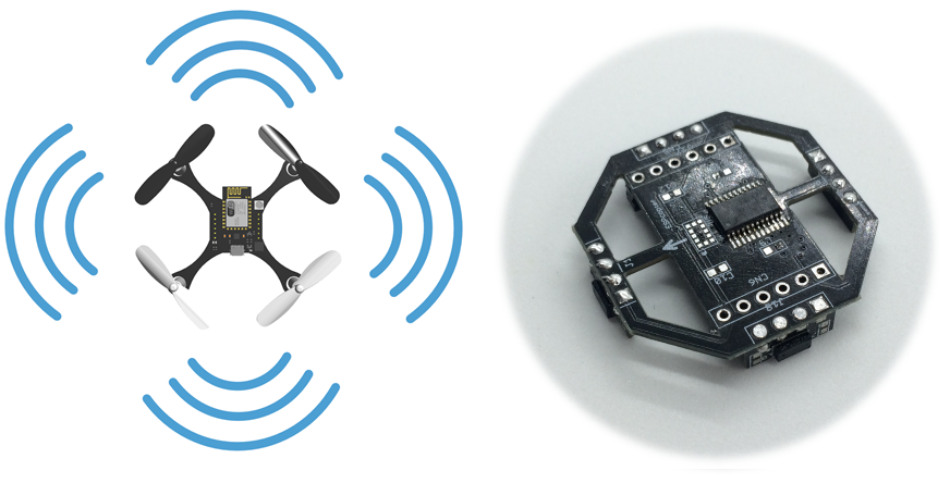
The optic flow module understands the drone’s movement via processing the images of the ground. In this way, drone can stay in the same location or it can move autonomously.

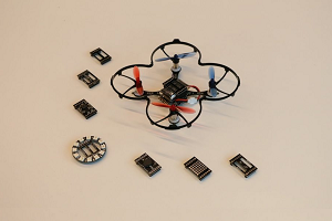
Optical Flow Module Connection:

Note: Module direction is important. It should be connected as the picture.
Optic Flow Blocks:

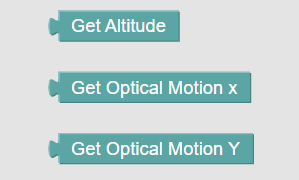
1-) Get altitude:
This block will return drone ESPcopter altitude data that come from the altitude sensor which is vl53l0x. The range of the sensor data is 0 - 1200mm.
2-) Get Optical Motion X:
This block will return drone ESPcopter optical flow sensor motion data on the x-axis.
3-) Get Optical Motion Y:
This block will return drone ESPcopter optical flow sensor motion data on the x-axis.
ESPcopter Development Modules
What are Development Modules?
Thanks to its modular structure, you can add new features to ESPcopter By using sensor shields.
ESPcopter Optical Flow Module:
The optical flow module measures the movement of the ESPcopter over the ground, allowing the drone to remain stable in the air and to perform autonomous tasks. You can reach additional information from this site: https://ardupilot.org/copter/docs/common-mouse-based-optical-flow-sensor-adns3080.html

Optical Flow Performance:
Optical Flow Module Connection:
Note: Module direction is important. It should be connected as picture.
ESPcopter Multi-Distance Module:
There are laser sensors on the multi-distance module with 1-meter detection distance facing forward, backward, right and left. With this module, you can do applications such as collision prevention, autonomous flight or hand control according to the distance to the walls.
Other Modules:
Note: Modules direction is important. The arrow direction should be a font of the ESPcopter

ESPcopter Neopixel Module:
There are 12 NeoPixels in this circular card. It can connect to the ESPcopter's top input pins.
You can use the NeoPixel module to make various light shows while flying with the ESPcopter.
ESPcopter Buzzer Module:
There is one buzzer in the buzzer module. It can connect to the ESPcopter's top input pins.
You can play music through the Buzzer module when you are not flying, and you can hear the warning sounds when you fly.
ESPcopter Temperature Pressure and Humidity module
This module has one BEM280 sensor. It can connect to the ESPcopter's top input pins.
You can use this module to record weather data while flying or you can send these data to your phone or computer over the internet in your IoT project.
ESPcopter Altitude Hold Module
This module has one VL53L0x sensor module. It can connect to the bottom input pins of the ESPcopter.
Using this module, you can measure the height of the ESPcopter up to 1.2 meters and automatically fix the height of the drone.

Neopixle
Neopixel Block:
Neopixel block is working by using RGB color format. RGB(RED GREEN BLUE) color format refers to a system for representing the colors. Red, green, and blue can be combined in various proportions to obtain any color in the visible spectrum.

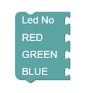
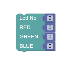
There are four inputs in the Neopixel Block these are Led No, RED, GREEN, and BLUE.
Neopixel Block
Neopixel Block İnputs:
1-) Led No:
Explanation: Selection of led on Neopixel Module
Input: integer
Range: 0 – 12
2-) RED:
Explanation: RGB color format for Red
Input: integer
Range: 0 – 255
3-) GREEN:
Explanation: RGB color format for green
Input: integer
Range: 0 – 255
4-) BLUE:
Explanation: RGB color format for blue
Input: integer
Range: 0 – 255
Examples:
1-) Changing color any of led:
- Turn on 0. led:

- Turn Off 0.Led:
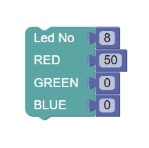
2- ) Setting brightness of LEDs
- Turn On 8. Led as a %20 RED:
- Turn On 8. Led as a %20 White:

3-) Changing color any of Whole Led:
- Change the color of whole LEDs:

- Change the color of whole LEDs by one by:
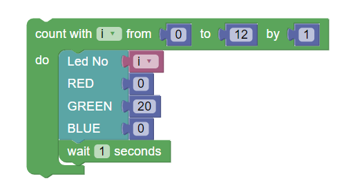
- Change the color of whole LEDs by one by. And then, turn off by one by:

- Change the color of whole LEDs to RED with %20 by one by. And then, turn off by one by. Make it continuously:
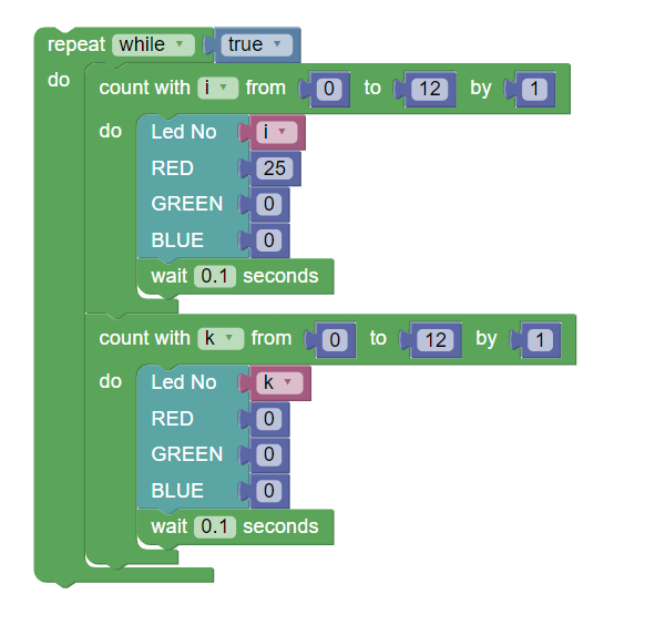
- Change the color of whole LEDs to RED by one by. And then, change the color of the whole LEDs to Green by one by. Change the color of the whole LEDs to Blue by one by. Make it continuously:


2-) Outputs
https://youtu.be/LPgAOTHfp50?list=PLN1j_JuvrwOJYA5TVu8JF2AL8OXq1tAB_
Output Blocks:
You can reach input blocks from the input section of the blockly website as you can see in the following picture.
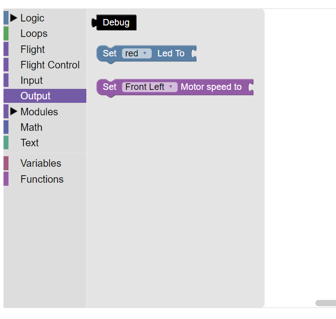
1-) Debug Block
Thanks to this block, we can read ESPcopter's whole current condition like battery voltage or which sensor is connected. Debug block is returning Strign. For this reason, you need to use it with a print block.

2-) Set Red / Green / Blue Led Block
Thanks to this block, we can turn on or turn off the board led color. This block has an input port. We can connect the boolean(True or False) block to this input.

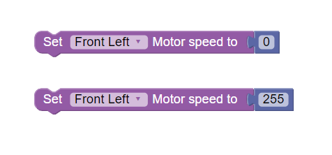
3-) Set Motor Speed Block
Thanks to this block, we can set ESPcopter motor speed separately. This block has an input port. We can connect the integer block to this input. The range should be 0 and 255. 255 is the max speed.
Note: Be careful when you are using this block. The drone may take off if you increase motor speed too much. Please slightly increase the motor speed.
1-) Inputs
https://youtu.be/0fU2GMVVK3Y?list=PLN1j_JuvrwOJYA5TVu8JF2AL8OXq1tAB_
Input Blocks:
You can reach input blocks from the input section of the blockly website as you can see in the following picture.

1-) Read Battery Voltage:

This block is basically reading battery voltage.
Example Projects:
- Print Battery Voltage to screen

- Print 10 times battery voltage to the screen

- Exercise: Convert drone battery voltage to percentage and print to screen
(Hint: output = ((voltage - battery_min) / (battery_max - battery_min)) * 100;)
2-) Read Accelerometer X Y Z Data:
An accelerometer is a device that measures the vibration, or acceleration of motion of a structure.

3-) Read Gyroscope X Y Z Data:

4-) Read Yaw Degree

5-) Read IMU Temperature


What is the ESPcopter?
Introducing Espcopter
After more than two years of continuing research, development and testing here is the most hackable and affordable mini-drone ESPcopter.

Our Corporate Supporters

What is the ESPcopter programmable mini-drone?
Espcopter it is unique small size mini-drone that is a wirelessly networkable, interactive and programmable drone.

Why Students Should Learn Drone Programming?
An important part of Drone technology is provided by the flight control software. If a suitable software can be written for a drone, it can be operated in all weather conditions.
 If students are trained in drone software, they can develop software in many areas such as defense industry, aerospace and aircraft technologies, especially drone, which is the technology of the future.
 How to program ESPcopter?

Blockly Programming
We developed a fully online blockly coding web site for students who are new to coding education.

Swarm Drone With Blocks
Arduino
Arduino is one of the most popular microcontroller coding languages of recent years. We have developed an open-source Arduino library for the ESPcopter.

ESPcopter can be programmed by using commands that are in the ESPcopter library. To the so you can learn Arduino programming from beginner to advanced.
ESPcopter Arduino SDK(Türkçe):
https://espcopter.com/wp-content/uploads/2016/09/espcopter-sdk.pdf
ESPcopter Arduino SDK(İngilizce):
https://espcopter.com/wp-content/uploads/2016/09/ESPcopter-SDKEnglish.pdf
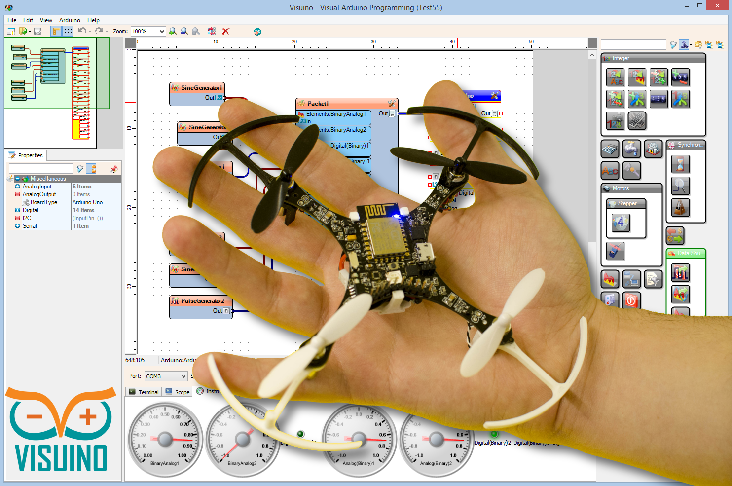
Visuino
Visuino is the latest innovative software from Mitov Software. A visual programming environment allowing you to program your ESPcopter boards.
How Can I Control ESPcopter?

Control with RemoteXY
RemoteXY is an IoT platform where you can make your own ESPcopter phone application by drag and drop over the internet. With this platform you can make your own control and develop it in various IoT applications.
Web address: www.remotexy.com

You Can Design Your Mobile Phone Control APP By Using RemoteXY

Computer Control With Processing App:
You can connect the ESPcopter to your computer through the application we have written in the Processing language. You can also control the ESPcopteri with gadgets such as mouse keyboard, game consoles that can connect to the computer.

What are the Technical Specifications of ESPcopter?

Thanks to its modular structure, you can add new features to ESPcopter By Using Sensor Shields
What are Development Modules?
ESPcopter Optical Flow Module:
The optical flow module measures the movement of the ESPcopter over the ground, allowing the drone to remain stable in the air and to perform autonomous tasks.
ESPcopter Multi-Distance Module:
There are laser sensors on the multi-distance module with 1-meter detection distance facing forward, backward, right and left. With this module, you can do applications such as collision prevention, autonomous flight or hand control according to the distance to the walls.
Other Modules:
ESPcopter Neopixel Module:
There are 12 NeoPixels in this circular card. It can connect to the ESPcopter’s top input pins.
You can use the NeoPixel module to make various light shows while flying with the ESPcopter.
ESPcopter Buzzer Module:
There is one buzzer in the buzzer module. It can connect to the ESPcopter’s top input pins.
You can play music through the Buzzer module when you are not flying, and you can hear the warning sounds when you fly.
ESPcopter Temperature Pressure and Humidity module
This module has one BEM280 sensor. It can connect to the ESPcopter’s top input pins.
You can use this module to record weather data while flying or you can send these data to your phone or computer over the internet in your IoT project.
ESPcopter Altitude Hold Module
This module has one VL53L0x sensor module. It can connect to the bottom input pins of the ESPcopter.
Using this module, you can measure the height of the ESPcopter up to 1.2 meters and automatically fix the height of the drone.
You Can Design Your Own Propeller Protector


Drone History
Drones – a nearly 100-year “Technology Revolution”
Unmanned Aircraft Systems (UAS), also known as “drones”, have become a public topic of interest and scrutiny over the past few years. Over the course of this chapter, I intend to describe how this technology came to be, what has prompted the technology explosion in the past few years,
Leonardo DaVinci 1452 -1519 – “Simplicity is the ultimate sophistication”

Leonardo di ser Piero da Vinci, more commonly Leonardo da Vinci, was an Italian polymath whose areas of interest included invention, painting, sculpting, architecture, science, music, mathematics, engineering, literature, anatomy, geology, astronomy, botany, writing, history, and cartography. He has been variously called the father of paleontology, ichnology, and architecture, and is widely considered one of the greatest painters of all time. Sometimes credited with the inventions of the parachute, helicopter, and tank, his genius epitomized the Renaissance humanist ideal.
Leonardo is revered for his technological ingenuity. He conceptualized flying machines, a type of armored fighting vehicle, concentrated solar power, an adding machine, and the double hull, also outlining a rudimentary theory of plate tectonics. Relatively few of his designs were constructed or were even feasible during his lifetime, but some of his smaller inventions, such as an automated bobbin winder and the machine for testing the tensile strength of wire, entered the world of manufacturing unheralded. He made substantial discoveries in anatomy, civil engineering, optics, and hydrodynamics, but he did not publish his findings and they had no direct influence on later science.
First Powered Flights

On December 17, 1903, Orville Wright piloted the first powered airplane 20 feet above a wind-swept beach in North Carolina. The flight lasted 12 seconds and covered 120 feet. Three more flights were made that day with Orville's brother Wilbur piloting the record flight lasting 59 seconds over a distance of 852 feet.
The brothers began their experimentation in flight in 1896 at their bicycle shop in Dayton, Ohio. They selected the beach at Kitty Hawk as their proving ground because of the constant wind that added lift to their craft. In 1902 they came to the beach with their glider and made more than 700 successful flights.
Having perfected glided flight, the next step was to move to powered flight. No automobile manufacturer could supply an engine both light enough and powerful enough for their needs. So they designed and built their own. All of their hard work, experimentation, and innovation came together that December day as they took to the sky and forever changed the course of history. The brothers notified several newspapers prior to their historic flight, but only one - the local journal - made mention of the event.
World War I – the game changer

Important developments in aviation during the first world war:
- Observation transformed into the bombing, then aerial warfare
- Advances in aviation were extreme in all aspects
- Conclusion of War led to an abundance of aviation technology available to be exploited for non-military purposes
Technology Evolution

“the pick up truck” – carried cargo/people - The Ford Trimotor (also called the "Tri-Motor", and nicknamed "The Tin Goose") was an American three-engined transport aircraft that was first produced in 1925 by the companies of Henry Ford and that continued to be produced until June 7, 1933.
Get above the weather to improve operational reliability and comfort - The Boeing Model 307 Stratoliner was the first commercial transport aircraft to enter service with a pressurized cabin. This feature allowed the aircraft to cruise at an altitude of 20,000 ft (6,000 m), well above many weather disturbances. The pressure differential was 2.5 psi (17 kPa), so at 14,700 ft (4,480 m) the cabin altitude was 8,000 ft (2,440 m). The Model 307 had capacity for a crew of five and 33 passengers. The cabin was nearly 12 ft (3.6 m) across. It was the first land-based aircraft to include a flight engineer as a crew member.
Faster, cheaper - The de Havilland DH 106 Comet was the first production commercial jetliner. Developed and manufactured by de Havilland at its Hatfield Aerodrome, Hertfordshire, United Kingdom headquarters, the Comet 1 prototype first flew on 27 July 1949. It featured an aerodynamically clean design with four de Havilland Ghost turbojet engines buried in the wings, a pressurized fuselage, and large square windows. For the era, it offered a relatively quiet, comfortable passenger cabin and showed signs of being a commercial success at its 1952 debut. signed for the civil aviation market, but also saw service with military units. The Ford Trimotor was sold around the world.
Today’s Manned Aviation

Today’s aviation, refinements of the technologies developed over the first 46 years of manned aviation. Lots of technology developments, particularly military, have been overlooked in this writing.
First Unmanned Aircraft?

Given manned aviation’s history, can anyone guess at when unmanned aviation truly started?
Before World War I, the possibility of using radio to control aircraft intrigued many inventors. One of these, Elmer Sperry, succeeded in arousing the US Navy's interest. Sperry had been perfecting gyroscopes for naval use since 1896 and established the Sperry Gyroscope Company in 1910. In 1911, airplanes had only been flying for eight years, and yet Sperry became intrigued with the concept of applying radio control to them. He realized that for radio control to be effective, automatic stabilization would be essential, so he decided to adapt his naval gyro-stabilizers.
The first test flights of an autopilot-equipped aircraft was in September, 1917, and took place with a human pilot on board to fly the takeoff. By November, the system successfully flew the aircraft to its intended target at a 30-mile (48 km) range, where the distance-measuring gear would drop a bag of sand. Accuracy was within two miles (3 km) of the target.
Clearly, though, more attention to flight testing the basic design was needed, particularly in the area of handling qualities. Sperry and his assistant, N. W. Dalton, obtained a Marmon automobile and mounted the Curtiss-Sperry Flying Bomb to the top of it. In this configuration, Sperry and his crew drove the Long Island Motor Parkway at 80 mph (130 km/h), one of the first examples of an open-air wind tunnel, and adjusted the flight controls to what they thought was the optimum settings. The design of the fuselage was changed slightly, lengthening it by two feet.
The Marmon was not only an excellent way to adjust the flight controls, it was realized that it would also be a good launching platform, and this was tried on March 6, 1918. The aircraft left the car cleanly, and flew in stable flight for the 1,000 yards (910 m) that the distance-measuring gear had been set for. For the first time in history, an unmanned, heavier-than-air vehicle had flown in controlled flight.
Another “Unmanned Torpedo”

Aphrodite and Anvil were the World War II code names of United States Army Air Forces and United States Navy operations to use B-17 and PB4Y bombers as precision-guided munitions against bunkers and other hardened/reinforced enemy facilities such as those targeted during Operation Crossbow.
The plan called for B-17 aircraft which had been taken out of operational service – various nicknames existed such as "robot", "baby", "drone" or "weary Willy" – to be loaded to capacity with explosives, and flown by radio control into bomb-resistant fortifications such as German U-boat pens and V-weapon sites.
It was hoped that this would match the British success with Tallboy and Grand Slam ground penetration bombs but the project was dangerous, expensive and unsuccessful. Of 14 missions flown, none resulted in the successful destruction of a target. Many aircraft lost control and crashed, or were shot down by flak, and many pilots were killed. However, a handful of aircraft scored near misses. One notable pilot death was Joseph P. Kennedy, Jr., the elder brother of US President John F. Kennedy.
The program effectively ceased on January 27, 1945 when General Spaatz sent an urgent message to Doolittle "Aphrodite babies must not be launched against the enemy until further orders".
Old Boeing B-17 Flying Fortress bombers were stripped of all normal combat armament and all other non-essential gear (armor, guns, bomb racks, transceiver, seats, etc.), relieving about 12,000 lb (5,400 kg) of weight. To allow easier exit when the pilot and co-pilot were to parachute out, the canopy was removed. Azon[9] radio remote-control equipment was added, with two television cameras fitted in the cockpit to allow a view of both the ground and the main instrumentation panel to be transmitted back to an accompanying CQ-17 'mothership'. The drone was loaded with explosives weighing more than twice that of a B-17's normal bomb payload. The British Torpex used for the purpose was itself 50% more powerful than TNT.
When the training program was complete, the 562nd Squadron had ten drones and four "motherships".
The Equivalent to Ford Trimotor?

The OQ-2 Radioplane was the first mass-produced UAV or drone in the United States. A follow-on version, the OQ-3, became the most widely used target aircraft in US service, with over 9,400 being built during World War II.
History[
The OQ-2 was originally a small radio controlled aircraft model designed by Walter Righter. The design, along with its engine design, was purchased by actor Reginald Denny, who had demonstrated another model to the US Army in 1940. Calling the new design the RP-2, he demonstrated several updated versions to the Army as the RP-2, RP-3 and RP-4 in 1939.
In 1940, the Army placed an order for 53 RP-4s, designating them the OQ-1, the OQ meaning a "subscale target". This small order led to a much bigger 1941 order for the similar RP-5, which became the US Army OQ-2. The US Navy also bought the drone, designating it TDD-1, for Target Drone, Denny, 1. Thousands were built, manufactured in a plant at the Van Nuys Airport in the Los Angeles metropolitan area.
It was at this factory on June 26, 1945 that Army photographer David Conover saw a young woman assembler named Norma Jeane Dougherty, whom he thought had potential as a model. She was photographed in the plant, which led to a screen test for Norma Jeane, who soon changed her name to Marilyn Monroe.[
The OQ-2 was a simple aircraft, powered by a two-cylinder two-cycle piston engine, providing 6 horsepower (4.5 kW) and driving two contra-rotating propellers. The RC control system was built by Bendix. Launching was by catapult only and recovered by parachute should it survive the target practice. The landing gear was used only on the OQ-2 versions as sold to the Army to cushion the landing by parachute. None of the drones including the improved variants shipped to the Navy had landing gear. The subsequent variants delivered to the Army did not have landing gear.
The OQ-2 led to a series of similar but improved variants, with the OQ-3 / TDD-2 and OQ-14 / TDD-3 produced in quantity. A number of other target drones were built by Radioplane (including licensed contractors) and competing companies during the war, most of which never got beyond prototype stage, which accounts for the gaps in the designation sequence between "OQ-3" and "OQ-14".
After WWII ended, various experiment were made with Radioplane target drones. In one experiment in 1950, a derivative of the QQ-3 Radioplane drone was used to lay military communication wire.
During the war Radioplane manufactured nearly fifteen thousand drones. The company was bought by Northrop in 1952.
Target Drone and Surveillance Asset
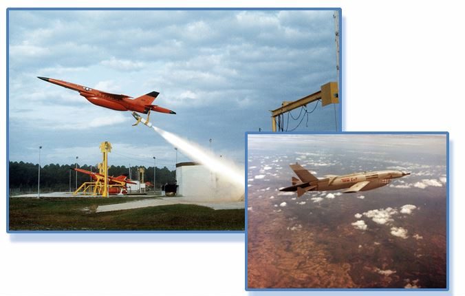
The Ryan Firebee was a series of target drones developed by the Ryan Aeronautical Company beginning in 1951. It was one of the first jet-propelled drones, and one of the most widely used target drones ever built
The Firebee I was the result of a 1948 US Air Force request and contract to Ryan for a jet-powered gunnery target. The first flight of the XQ-2 Firebee prototype took place in early 1951. The drone featured swept flight surfaces and a circular nose inlet. The initial models had distinctive "arrowhead" shaped end plates on the tailplane. The Firebee could be air-launched, specially modified Douglas A-26 Invader bombers being first used; or ground-launched with a single RATO booster.
The modern military “drone”….

The General Atomics MQ-1 Predator is an unmanned aerial vehicle (UAV) built by General Atomics and used primarily by the United States Air Force (USAF) and Central Intelligence Agency (CIA). Initially conceived in the early 1990s for aerial reconnaissance and forward observation roles, the Predator carries cameras and other sensors but has been modified and upgraded to carry and fire two AGM-114 Hellfire missiles or other munitions (Unmanned combat aerial vehicle). The aircraft, in use since 1995, has seen combat over Afghanistan, Pakistan, Bosnia, Serbia, Iraq, Yemen, Libya, Syria, and Somalia.
The USAF describes the Predator as a "Tier II" MALE UAS (medium-altitude, long-endurance unmanned aircraft system). The UAS consists of four aircraft or "air vehicles" with sensors, a ground control station (GCS), and a primary satellite link communication suite.[4] Powered by a Rotax engine and driven by a propeller, the air vehicle can fly up to 400 nmi (460 mi; 740 km) to a target, loiter overhead for 14 hours, then return to its base.
Following 2001, the RQ-1 Predator became the primary unmanned aircraft used for offensive operations by the USAF and the CIA in Afghanistan and the Pakistani tribal areas; it has also been deployed elsewhere. Because offensive uses of the Predator are classified, U.S. military officials have reported an appreciation for the intelligence and reconnaissance-gathering abilities of UAVs but declined to publicly discuss their offensive use.[5]
Civilian applications have included border enforcement and scientific studies, and to monitor wind direction and other characteristics of large forest fires (such as the one that was used by the California Air National Guard in the August 2013 Rim Fire).
The Northrop Grumman RQ-4 Global Hawk is an unmanned (UAV) surveillance aircraft. First flight in 1998. It was initially designed by Ryan Aeronautical (now part of Northrop Grumman), and known as Tier II+ during development. The Global Hawk performs a similar role as the Lockheed U-2. The RQ-4 provides a broad overview and systematic surveillance using high-resolution synthetic aperture radar (SAR) and long-range electro-optical/infrared (EO/IR) sensors with long loiter times over target areas. It can survey as much as 40,000 square miles (100,000 km2) of terrain a day.
The Global Hawk is operated by the United States Air Force. It is used as a high-altitude platform covering the spectrum of intelligence collection capability to support forces in worldwide military operations. According to the United States Air Force, the superior surveillance capabilities of the aircraft allow more precise weapons targeting and better protection of friendly forces. Cost overruns led to the original plan to acquire 63 aircraft being cut to 45, and to a 2013 proposal to mothball the 21 Block 30 signals intelligence variants.[1] Each aircraft was to cost US$60.9 million in 2001,[2] but this had risen to $222.7 million per aircraft (including development costs) by 2013.[1] The U.S. Navy has developed the Global Hawk into the MQ-4C Triton maritime surveillance platform.
Estimated to cost 28K $ /hour of flight
What is the difference in these technological evolutions?
Manned Aviation
- 15 years to commercial adoption
- Mail service, passenger and cargo transportation
Unmanned Aviation
- 76 years of military development with little commercial penetration
- Transportation has not been the niche for commercial UAS!
The Unmanned System Revolution
The promise
- Information is the key deliverable (currently)
- The systems in use have a much lower “footprint” and initial cost than manned alternatives.
The revolution enablers
- Computing
- Navigation systems
- Sensors
- Cell Phones
Today’s Ground Breaking Systems